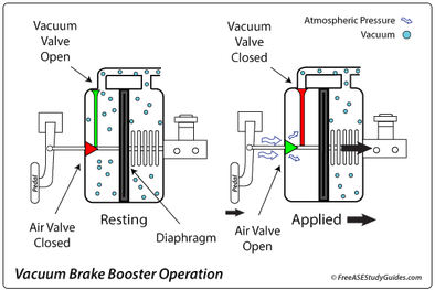
Diagram of vacuum booster system.
Von einem Mystery-Man-Autor
Last updated 01 Juni 2024

Download scientific diagram | Diagram of vacuum booster system. from publication: Braking force decoupling control without pressure sensor for a novel series regenerative brake system | Regenerative braking can save energy consumption greatly for electric vehicles. For a series regenerative brake system, it is foundational to make the hydraulic braking torque and braking force decoupled and to provide the same pedal feeling as conventional braking system. In | Pressure Sensors, Sliding Mode Control and Anti-lock Braking Systems | ResearchGate, the professional network for scientists.
Vacuum Brake Booster: Hard Pedal Problems Diagnosis

Vacuum Boosters

Power Brakes - Vacuum Assist - Explained

Diagram of vacuum booster system.
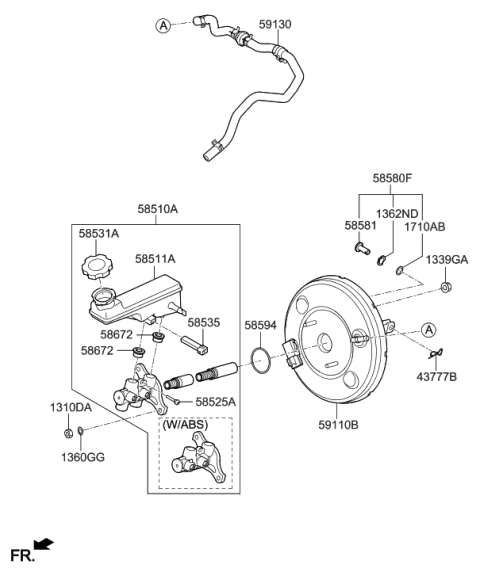
59130-H9280 Genuine Hyundai Hose Assembly-Brake Booster Vacuum
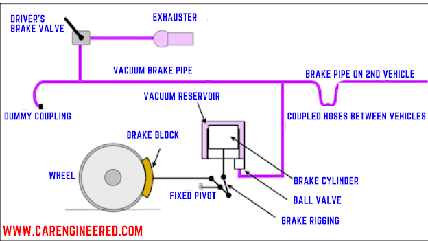
VACUUM BRAKING SYSTEM — Carengineered.com, by Carengineered

Series III vacuum hose routing for brake booster - E-Type - Jag-lovers Forums
Brake Booster Valve (test and part no?)
★【Fitment】Vacuum Power Brake Booster fit 1997- 1999 for Chevrolet C1500/ K1500, 1997- 2000 for Chevrolet C2500/ K2500, 1997- 1999 for GMC C1500/

DRIVESTAR 54-71085 Vacuum Power Brake Booster without Master Cylinder, fit 1997-1999 for Chevrolet/GMC C1500 K1500, 1997-2000 for Chevrolet/GMC C2500

Bosch Hydro-Max Components and Hose Diagram
für dich empfohlen
 Brake Booster - AISIN ASIA14 Jul 2023
 Cardone 54-74829 Remanufactured Vacuum Power Brake Booster without Master Cylinder (Renewed) : Automotive14 Jul 2023
 7 Street Hot Rod Power Brake Booster & Master Cylinder Zinc Brakes Custom Car14 Jul 2023
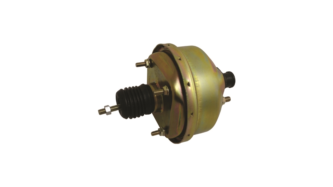 Compact 7 Single Diaphragm Brake Booster - Vacuum - Plain14 Jul 2023
- Cardone 54-74829 Remanufactured Vacuum Power Brake Booster without Master Cylinder (Renewed)14 Jul 2023
 A1 Cardone 54-73181 Remanufactured Vacuum Power Brake Booster without Master Cylinder, Grey (Renewed)14 Jul 2023
 Power Brake Booster 8.514 Jul 2023
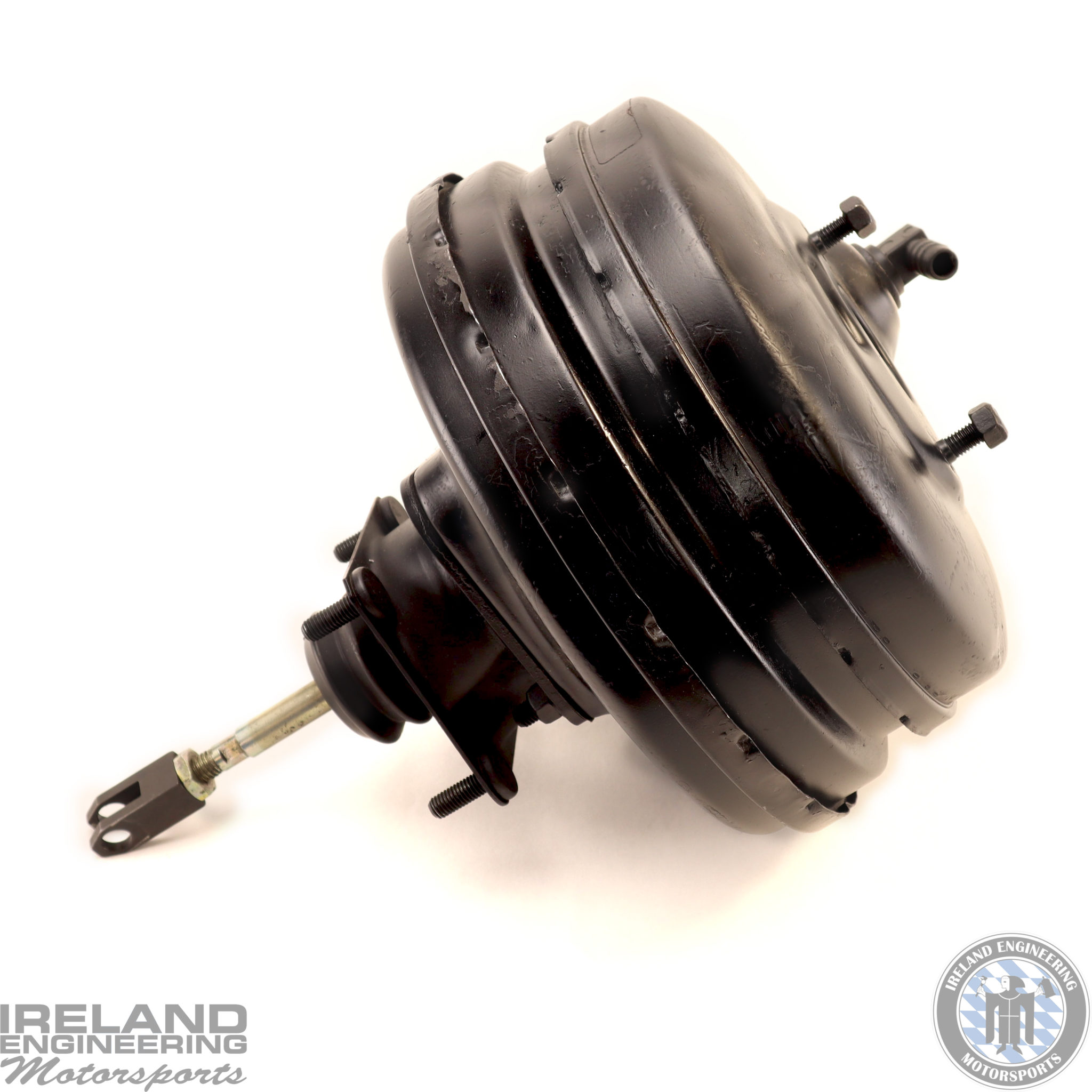 Brake Booster Rebuild Service - E3014 Jul 2023
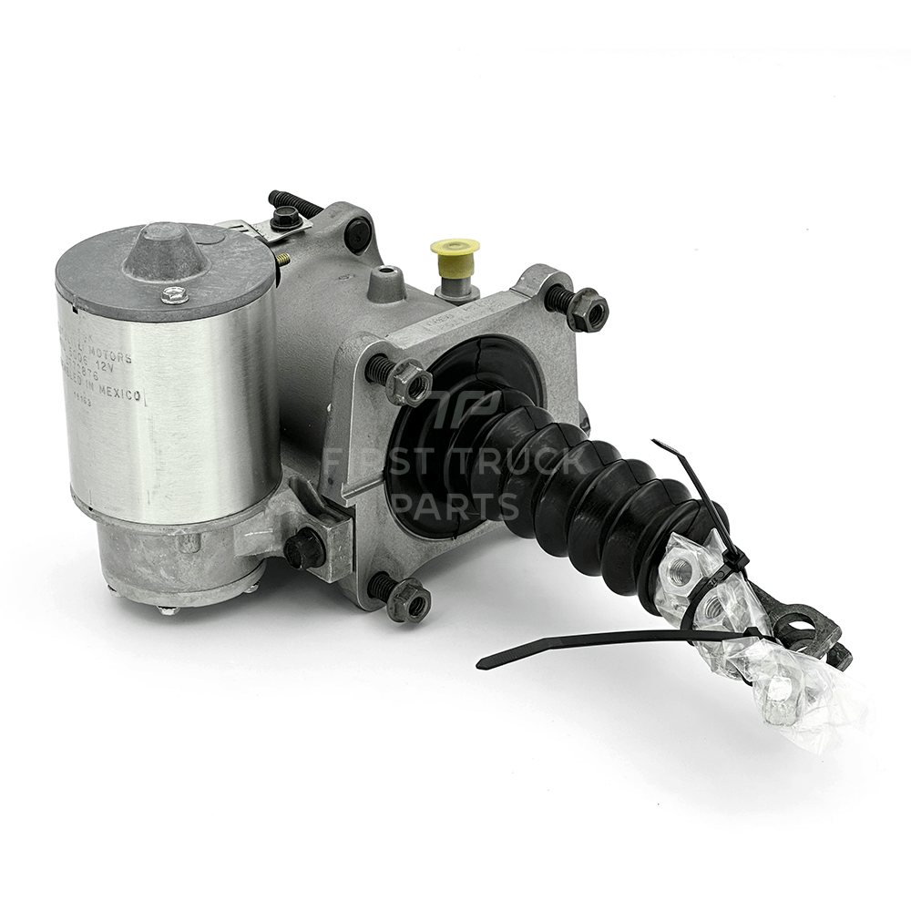 P/N: 2505685C91 Genuine International® Brake Booster14 Jul 2023
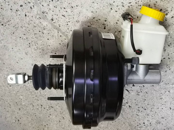 GM Brake Booster / Hydrovac with Master Cylinder for Chevrolet14 Jul 2023
Sie können auch mögen
 For Tesla Model Y 2020-21 Carbon Fiber Side Vent Window Scoop Louver Cover Trim14 Jul 2023
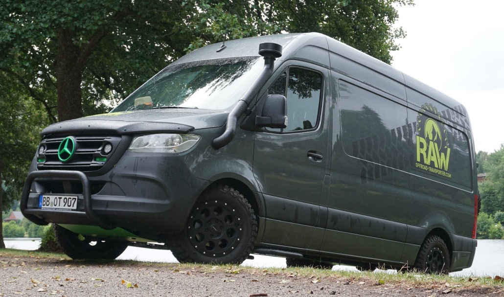 Offroad-Transporter - Offroadumbau für den MB Sprinter14 Jul 2023
 220nF, 250V-, 20%, 0,22µF, axial, Kondensatoren, MKT, RFT, TGL43199, 20 Stück14 Jul 2023
 Volvo FH Zacken Aufkleber14 Jul 2023
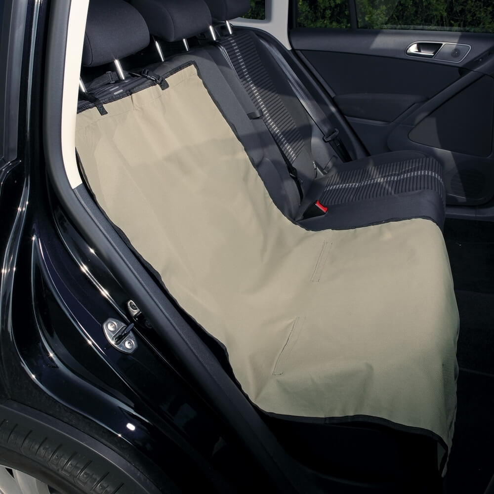 Autositzschutz in beige14 Jul 2023
 Adrianne Lenker's Radical Honesty14 Jul 2023
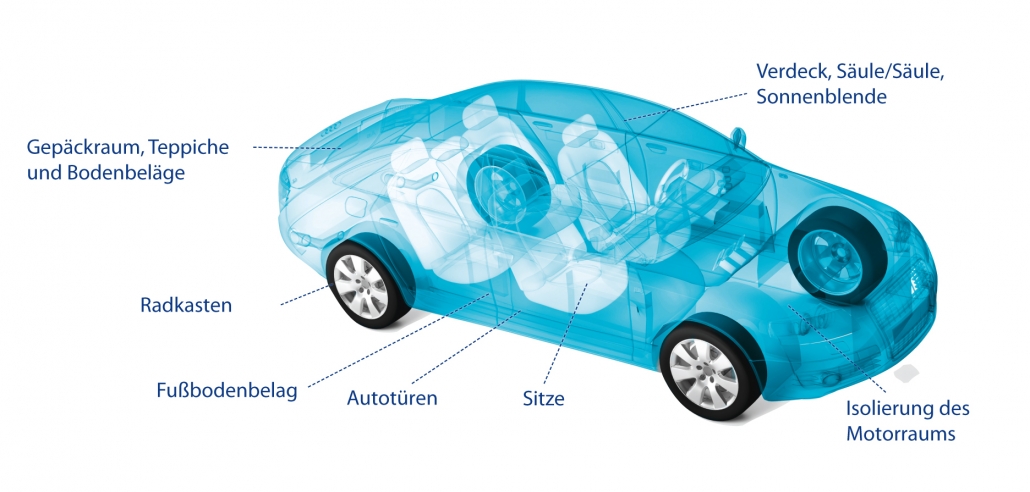 Pulcra Nonwovens14 Jul 2023
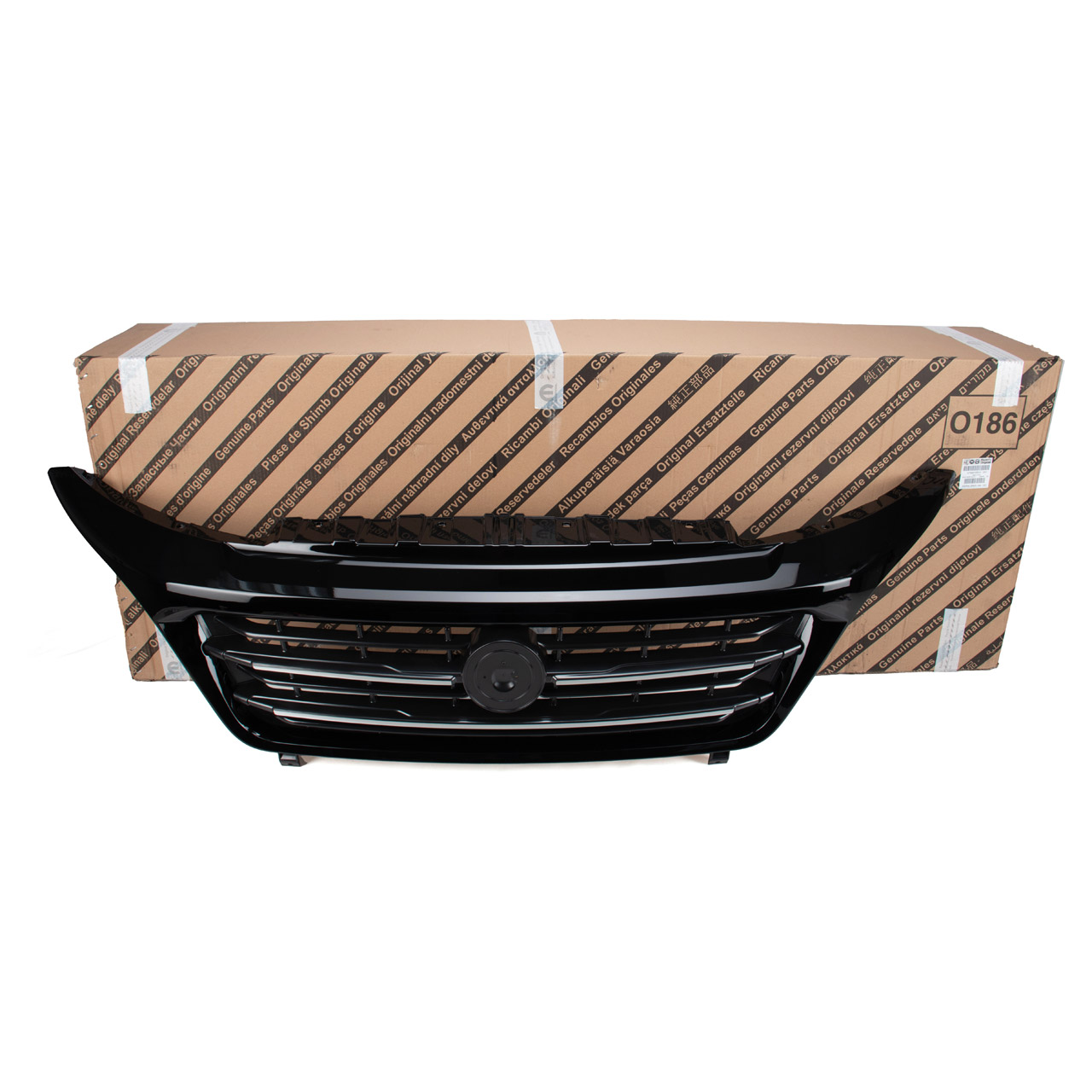 Original FIAT Kühlergrills - 73561592414 Jul 2023
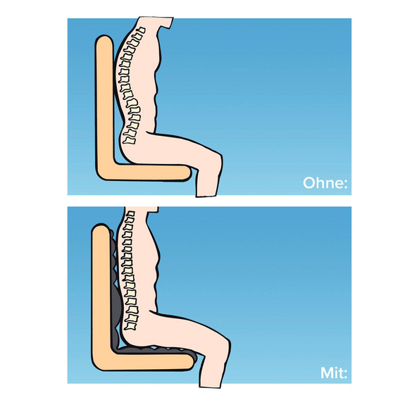 Auto Leder- Sitzbezug 7280900014 Jul 2023
 Schwangerschaft Gurt Auto (2x) in Stuttgart - Mühlhausen14 Jul 2023