Schematic diagram of a basic Step-Up converter integrated in a
Von einem Mystery-Man-Autor
Last updated 12 mai 2024

Download scientific diagram | Schematic diagram of a basic Step-Up converter integrated in a photovoltaic generator. PV is a photovoltaic panel, PWM is the Pulse Width Modulator. C1, C2, Rp, Rs, L1, D1 and M1 are the discrete elements constituting the electronic circuit (see the text). from publication: Basic MOSFET Based vs Couple-coils Boost Converters for Photovoltaic Generators | Considering the optimization of a photovoltaic system, several studies show the advantage in the choice of a distributed structure. For such structures small power converters such as the boosts and buck converters appear as most appropriate. We have analysed the efficiency of | MOSFET, Photovoltaics and Boost | ResearchGate, the professional network for scientists.

Boost Converter: Basics, Working, Design & Application
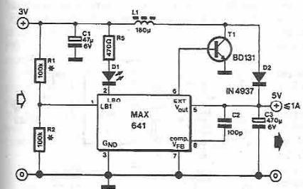
MAX641 high current step-up converter under Repository-circuits

Boost converter - Wikipedia

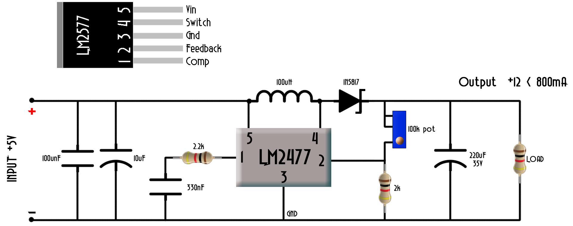
LM2577 Boost Converter circuit, Step up, Datasheet
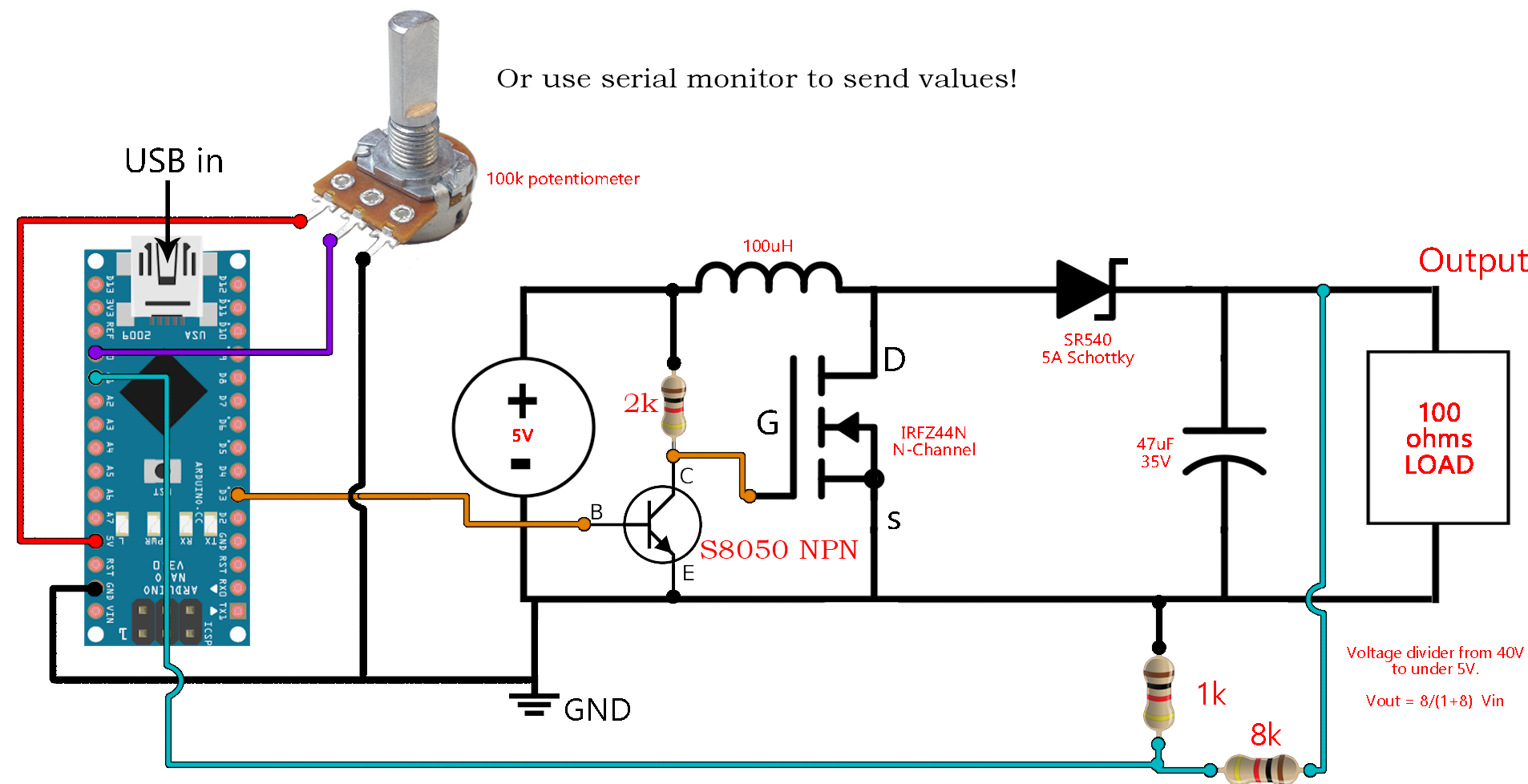
DC to DC boost converter circuit homemade

High Voltage Boost and Inverting Converters for Communications
DC to DC boost converter circuit homemade

Circuit of High-step-up dc-dc converter

Micropower 600kHz Fixed-Frequency DC/DC Converters Step Up from a
für dich empfohlen
 Step Up 12V to 27.5V DC to DC Converter14 Jul 2023
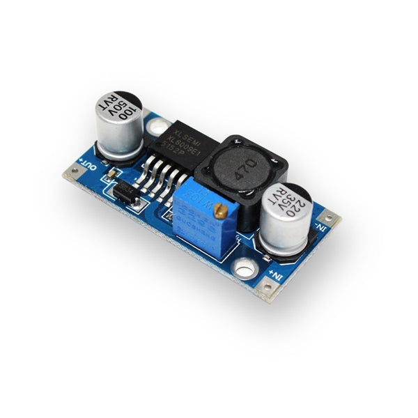 XL6009E1 Step-Up Adjustable DC-DC Switching Boost Converter14 Jul 2023
 5A DC-DC Step Up Power Module Boost Volt Converter 3-35V to 5V 6V 9V 12V 24V 36V14 Jul 2023
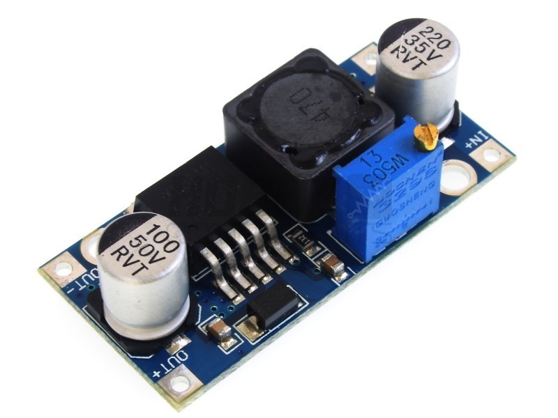 XL60009 DC-DC Step-up Boost Converter14 Jul 2023
 150W Boost Converter Schematic14 Jul 2023
 USB Step-up Boost Converter DC 5V to 9V 12V - DFRobot14 Jul 2023
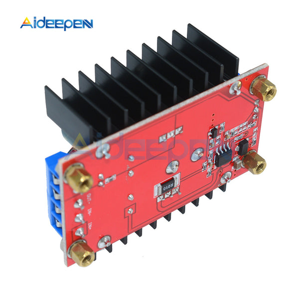 100W 120W 150W DC DC Boost Converter Step Up Power Supply Module 10 32 – Aideepen14 Jul 2023
 Boost Converters - DC to DC Step Up Voltage Circuits14 Jul 2023
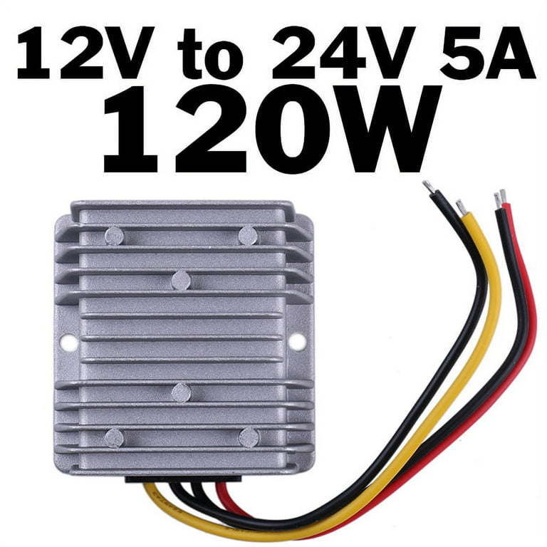 DC 12V to DC 24V 5A 120W Step Up Boost Converter Voltage Regulator14 Jul 2023
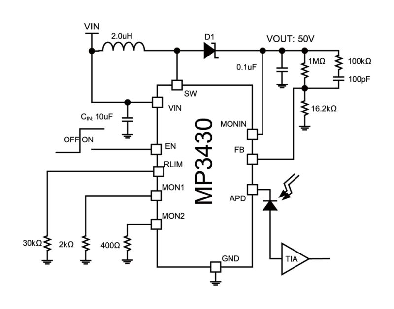 MP3430 90V Step-Up Converter with APD Current Monitor (1:10 or 114 Jul 2023
Sie können auch mögen
 OKESYO 300A Sammelschienen Verteilerblock mit Wasserdichter14 Jul 2023
 Dachbox Atera Casar XL Lava Structured14 Jul 2023
- OSRAM NIGHT BREAKER H4-LED, jusqu'à 230% de lumi…14 Jul 2023
 Crullé Antibeschlag-Reinigungsspray für Brillen für 30ml14 Jul 2023
 Funktionsweise der Photovoltaik-Anlage14 Jul 2023
 140*80cm Sommer Auto Windschutzscheibe Sonnenschutz Frontscheiben14 Jul 2023
 Audi S3 8V Türbeleuchtung LED auf RS performance Nachrüstpaket14 Jul 2023
- The Story Behind our Logo14 Jul 2023
- Pyros Aschenbecher für den Balkon14 Jul 2023
 Kupplung Kupplungssatz für Peugeot 206 Schrägheck 1.6 16V Baujahr14 Jul 2023